July 2020
The patient presented following a failed recovery attempt on an Implant One Series 200 implant in the #3 site.
This implant was placed in September of 2013 and had suffered a fractured abutment in July of 2020, which was recovered and subsequently restored. There was one prior documented mechanical issue with a loose abutment screw which had been retightened. Due to this prior screw episode, on advice from the company’s technical support, the abutment screw, was torqued to 35Ncm. Unfortunately, in July of 2024 when the crown became loose again, his general dentist tried tightening the abutment screw again, but it fractured. I suspect the implant abutment had already fractured and the crown was only retained by the abutment screw, a common finding in other abutment fracture cases of similar mechanical design. He then went back to his prior dentist who had successfully recovered the first fractured abutment. Using the Implant One recovery tooling, he was unsuccessful when the abutment fragment could not be distracted out. He then tried to recover the abutment screw, with the abutment fragment still in place, but was unsuccessful with this approach as well. The patient was then referred to my office.
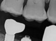
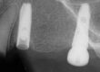
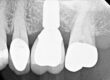
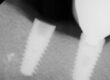
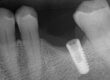
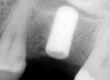
Preop images prior to any recovery efforts
")
")
")
")
Appointment one in my office following the prior unsuccessful recovery
There were two aspects to this recovery: recovery of the abutment fragment first and then address retrieval of the remaining screw fragment. The prior eccentric screw retrieval effort had damaged some implant threads, but it was unclear as to the extent. The retrieval of the abutment fragment was complicated, as some of the prior efforts had reduced the wall thickness to the point that it limited routine retrieval options. This prevented the use of distraction techniques typically employed when confronted with a fractured abutment fragment in a steep walled conical interfaced implant. As the abutment wall was very thin at 3:00, this allowed that section to be slightly imploded from the implant wall, using a mallet and a small root tip pick. The abutment loosened and was recovered. After retrieval of the abutment, a 6 degree (12 degree inclusive) conical connection, was evaluated and the implant interface was free of defects. There was one rounded hex corner at 2:00 in the indexing feature, which had been reduced by the prior drilling attempt on the abutment screw. However, this amount would not be a factor going forward and will not affect the future restorative outcome. An impression was made of the implant interior to assist in evaluating the thread issues. As planned, the first appointment goals were exceeded, and the next step was engineering and machining a precision drill guide, following receipt of implant analogs and a titanium temporary abutment from Implant Logistics.
The preop case as it presented to our practice
")
")
")
Post abutment fragment recovery
")
Left, impression of a Series 200 analog. As there were no actual implants to internally evaluate, the analog was the next best option. However, analogs are often drilled and / or threaded deeper to accommodate lab screws. The next four images are from an intraoral impression, post abutment recovery. The images are rotated progressively 90 degrees. The right two images are the recovered abutment, side and end views. These show the perforated sidewall locations which occurred in the initial recovery attempt by the patinets’ previous dentist.
")
Appointment two in my office
With the drill guide made, this second appointment was started by securing the drill guide to the adjacent teeth with Orthocril LC resin. For an in depth instruction sheet on how to construct this guide, it is posted on this website under: Setting up a custom drill guide with Ortho resin. This creates a removable guide which can be removed and replaced with precision. Guide retrieval allows for drill chip hygiene and progressive microscopic evaluation. Custom left hand drills were used, starting with a .8mm drill and progressing to a 1.1mm drill. The threading in this implant is a 0-80 English thread, somewhat unique in the implant industry. For size reference, the closest metric thread is the slightly larger M1.6x.35. It quickly became obvious this screw fragment was so entangled with the implant threads, it would have to be retrieved in pieces. Therefore, the appointment was terminated so the correct diameter predrill, and 0-80 taps could be procured and prepared with custom adapters for the ISO 1797 latch connection. This allows the use of a Bien Air handpiece, to take advantage of direction, speed, torque and auto reversing controls. Designing the adapters outside diameter sized to the drill guides internal diameter, allows both drill and tap operations to be fully guided. This keeps the machining operations concentric in the implant as the body of the screw is removed to the predrill diameter. The implant threads can then be cleared with the modified 0-80 plug taps. The goal is to keep the original threads as intact as possible, especially in the very critical time while the partially damaged lead threads are cleared.
")
")
Appointment three in my office
With the correct #56 predrill and 0-80 plug taps modified to integrate with the custom drill guide, the process of cleaning the threads was started. First the bore was enlarged to the predrill diameter with the #56 drill. This cleared any residual screw core leaving only the remaining male screw threads. At this point, it was finally becoming clear there were significant threads to be gained. This is because the bore sidewalls looked smooth in many areas after the #56 drill, with only some areas of prior off axis drilling efforts lateral to the bore. The modified 0-80 plug taps were then introduced to pick out the residual male screw threads. This is a delicate time in the recovery, as the tap has to find the existing implant threading and get “clocked” into it, otherwise the tap will start creating a thread independent of the existing implant threads. Generally, this is a slow, hand driven process, retrieving one small chunk of screw thread debris at a time, at least at first. As the tap gains stability and guidance from the newly exposed implant threads, the process gets easier and more predictable, as long as the tap stays intact. The key to tapping is slow and steady progression with frequent tap cleaning. Progressing too quickly can create a thread fragment that becomes trapped behind the tap, preventing counterclockwise tap removal. The locked tap tip then is at risk of fracture. If fractured, the tap end will be firmly wedged into the screw thread debris and is virtually impossible to retrieve without further implant damage. The steel in the tap is hardened to almost brittle, so even a sharp carbide drill has a tough time cutting through it.
When the threads were as clean as possible, a last postop impression was made to evaluate what had been exposed. A titanium temporary abutment was seated, screw tightened without an issue and retrieved. A silicone plug was placed as there was no healing abutment and he was referred back to his dentist to continue with replacement of his restorative.
")
")
")
")
")
The left two images show thread fragments displaced from the implant. As the process progresses, these fragments tend to grow in size.
")
Post op thread evaluation
")
This recovery turned out to be a Type V in my screw retrieval algorithm. Type V has generally occurred after a prior failed recovery effort when the remaining screw fragment, often with distorted implant threads, forces a complete drill out. However, the damage is not so severe as to preclude the use of OEM restorative components, following Implant Mechanical Rescue. I believe the prognosis progressing forward is good, even though there was some prior implant thread damage. This implant obtains significant abutment to implant stability due to the deep conical connection. In fact, I was very surprised to review in the history that there was an initial loose abutment screw, after only 9 months in function. I have recovered over 250 Ankylos fractured abutment cases where the inclusive conical angle is very similar,11.4 vs 12 degrees, and I have never seen a case with an abutment screw issue, without a fractured abutment being present first.
On a final note, when reading the previous treatment record from his original restorative doctor, in a letter to the patient on 7-2-20, it related an Implant One tech support advised 35NCm torque on the new abutment screw due to a prior history of screw loosening. I would take exception to this recommendation for the following reasons: this is a small screw, slightly smaller than a M1.6, and it also has a pan head, not tapered. Understanding screw dynamics, it is desirable to achieve vertical stretch in the screw, preload, but not excessive torsion in the threads. Obviously, both occur due to thread friction. The formula is total torque – head friction = thread torque. Thread torque, that creates torsion is bad, and when excessive can break a screw on delivery. As an example, Straumann torques the bone level M1.6 RC and NC screws to 35 Ncm, but the heads are tapered, so some of the torque is bled off before reaching the threads. Another example is in the Astra EV line. All of the screws are placed at 25 Ncm, so there is less error in the field. The 3.0 implant has a M1.4 screw and the 4.8 and 5.4 implants have M2 screws. The M1.4 screw has a very tapered head, and the taper gets flatter in the M1.6 and M1.8 screws and is totally flat in the M2 screws. Screws should be torqued to about 75-90% of the yield point. The yield point is where the metal in the screw transfers from elastic to plastic deformation. Once a screw hits the yield point, it cannot deliver any more preload, it just stretches and gets permanently deformed and weaker. That is why a M1.4 flat head prosthetic screw is torqued to 15Ncm. Screw loosening and fracture is a function of abutment connection stability. This implant has a very stable connection in the deep 12 degree conical connection. The weak link in this system, as it is in the Ankylos system and another basic copy, the Neodent CM, is the minimal diameter of the abutment at the implant top. That is the reason abutment fractures occur at the implant top, where stress concentrates in molar applications. It’s hard to beat physics. Therefore, I believe the 20Ncm torque value is correct, as long as the conical connection is engaged.
For additional information regarding these procedures, there are additional case studies posted on our website.
Charlie Mastrovich, DDS