August 2025
A Routine Type I Case Transformed Into a Type V or VI When Initial Recovery Efforts Failed
Introduction
This case study has been posted as a clear example of how an uncontrolled screw recovery can quickly progress from a routine, straightforward case into a very challenging recovery with serious case complications. Specifically, it illustrates how the lack of initial microscope guidance for adequate diagnosis and progress tracking, the use of tooling with inadequate precision, and lack of operator understanding, all contributed to the resulting outcome.
History
The patient was referred for to our practice by both her general dentist and the first oral surgeon she saw, for retrieval of a fractured abutment screw fragment from an Astra 3.5 Tx (Aqua) implant in the #12 site. This implant was placed on 07.25.2022 by a different oral surgeon, now retired, along with #14, an Astra TX Lilac. Additionally, it was supporting the anterior end of a 3 tooth implant supported fixed partial denture (FPD) from 12i-14i. When the patient presented to resolve another dental issue, her general dentist noted looseness in the bridge. Unfortunately, due to a medical emergency, she could not immediately address the loose bridge issue, and when she could it was discovered the abutment screw had fractured. Her general dentist tried to recover with hand instruments and thought there was mobility in the screw fragment, but he could not retrieve it. He then referred the case to the first oral surgeon, near his office. In a short appointment, he attempted retrieval using an explorer but could not determine whether the fragment was mobile or not, and then lightly touched it with an Astra fragment fork, but without any result. He then said he referred the case to my office. However, after that appointment she was encouraged by her general dentist to see another oral surgeon, who is the implanting oral surgeon’s successor. According to the patient, he worked on retrieving the screw fragment for about 2 hours. In a phone call, he did mention his attempt included the use of the Salvin recovery tool kit. When he was unsuccessful, the patient appointed in our office to evaluate whether the implant could be saved.
")
")
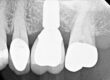
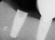
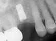
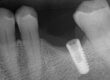
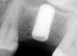
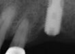
Preop radiograph from the general dentist. We do not have the exact date for this image, but I believe it was taken prior to any recovery attempts. Note the fragment position is above the first implant thread, as viewed in the right cropped image. Green arrow is the top of the implant threading, the yellow arrow is the top of the screw fragment. A Type I or II case in our fractured screw algorithm.
")
")
")
The above three images are duplicates of the preop clinical image, which is a focus stacked 25x microscope image. It clearly shows a very eccentric prior recovery effort, red circle, in the 10-12 o’clock position. The right image is the same photograph with yellow arrows to show additional eccentric efforts. The green circle is concentric on the minor diameter of the screw. The concern is any effort outside of the green circle, would be invading implant structure. When prior recovery efforts have wandered eccentrically into the implant, a decision has to be made as to the severity of the damage and future prognosis of the implant. Due to potential compromised mechanical stability, even if a successful recovery can be accomplished without incurring additional damage, the question is will the implant still be stable? Unfortunately, this decision, in this particular situation, is not easily made. Working extensively to save an implant with considerable damage could be an unwise decision, due to time and expense. However, condemning the implant prematurely might also be proceeding into a difficult clinical scenario. To help sort this out to the next level, an impression was made of the internal aspects of the implant and evaluated microscopically. The photographs shown below were processed post appointment.
")
The end photographs are of a new Astra Tx aqua implant as an undamaged control. The center four images were taken from the preop impression before any recovery efforts in this office. The impression was rotated 90 degrees in each subsequent view.
What can be seen: The prior recovery effort had no possibility of succeeding, as the effort was clearly eccentric and solidly into implant structure. Any retrieval efforts could not rotate the remaining fragment up, because the extractor would be engaged into the implant as well as the screw fragment. If pursued hard enough, additional torque would result in a fractured recovery instrument. Four of the twelve indexing splines had been eliminated, but eight still remain. Eight is enough to provide a positive index for another abutment. There was no visible damage to the top 11 degree conical connection, which is the critical element that supplies the stability for the abutment to implant connection. That is good news. The problem is how much thread has been lost and is it enough to establish stable preload for the abutment screw?
What cannot be seen: Looking at the impression, the lack of impression material indicates there is still a lot of screw fragment left in the implant, both in length and on the side opposite of the damage. This area is illustrated with yellow arrows.
With the above assessment, the decision was made to cautiously proceed in an attempt to get the drilling process concentrically on track, knowing it was highly probable this screw fragment would need to be retrieved in pieces. #11 had already been diagnosed for extraction, so the possibility of using another implant in the #11 site along with #12, could offer the needed stability on the anterior end of the prosthesis. This scenario would be extremely helpful, as this restoration had failed in under 3 years. The original restoration was fabricated by Glidewell, on Glidewell components.
Treatment
With the amount of off-axis drilling, achieving a concentric starting spot is difficult. If the spot is not clean enough, the first drill will tend to be pushed laterally and the drill will start, and progressively drift, more eccentrically. This is illustrated in the following photograph sequence.
")
")
")
The above sequence illustrates the issue of defining the spot. Retrospectively, the spot could have been more toward 5 o’clock, but under normal circumstances this would have been more than adequate. Starting the .8mm bore is the next step in the sequence.
")
")
.8mm slightly inside of the spot and is cropped in the second image. This photograph is centered on the visible outline of the fragment.
")
")
.8mm bore is deepened with a slight progressive drift toward 9 o'clock from image 2 to 4. Clinically, this was hard to appreciate at this level of detail with the top 1/2 of the screw outline missing.
")
The end photographs are of a new Astra Tx aqua implant as an undamaged control. The center four images are of the postop impression, again turned 90 degrees to evaluate each side.
While significant threads have been cleared, there was some additional internal thread damage due to the difficulty in achieving and keeping the boring operation concentric. This can be viewed on the same side in the threads, apical to the prior significant eccentric drilling. This was caused by deflection of the enlarging drills, terminating with a 1.25mm predrill, when they were introduced to eliminate the screw core. This step is mandatory prior to introducing a tap, as a tap cannot negotiate an obstruction, other than eliminating the small male thread fragments. There is no room for concentric error at that diameter. The amount of thread blunting can be visualized in views 1 and 3, with the right and left arrows. This blunting appears as a filled in area by the impression material.
Conclusion
This case illustrates the need for precision guided tooling, microscope guidance at each step in the process, and an adequate skill set to understand the limitations as they present, to make corrections when proceeding. To date, in previously posted cases, I have listed six reasons a drill may not start and or stay concentric, even if a drill guide is used. Without a drill guide, free hand drilling is next to impossible to be predictably accurate, but using a guide is not a guarantee of concentric drilling either. This list will now have a seventh reason, and the new list is below.
- The guide was not made concentric, so the guiding bores do not align with the interface.
- The tolerance fit of the drills to the guide is not adequate, which allows for the drill to wander and drill
eccentrically. - The tolerance fit of the guide to the implant interface is not adequate, again allowing eccentric drilling
- The handle system, while designed to hold the guide stable, often does just the opposite, if the tolerance fit of the guide to the implant is not secure or stable. Many implant interfaces do not offer enough stability to resist the torsional leverage a handle system can exert.
- There was no confirmed, concentric starting point with a spotting drill, without which the drill is allowed
to wander while starting the bore. - As these drills are small and flexible, the drills can flex, especially when starting the bore. This is a big reason for fractured drills, as this eccentric drilling side loads the drill. As the bore is deepened, the loading increases, fracturing the drill and if not, the eccentric error increases.
- When working toward a concentric position following a previous eccentric recovery attempt, the drill
can deflect off of the opposite, intact side wall in a comparable way that it will deflect off an incomplete, eccentric starting spot. Countering this tendency, and to avoid this issue, requires the knowledge that it could be a possibility. It is technique sensitive to avoid, and can occur even with the use of a precision guided system.
As noted earlier in this report, a Salvin recovery kit was used for guidance in the previous recovery effort. Unfortunately, this system did not provide the necessary precision to avoid the eccentric drilling issue outlined above. I have run into this issue previously in another case where the Salvin kit was used, and with the same eccentric result. Unfortunately, this limited kit does not have a guide sleeve that seats accurately into an Astra aqua implant interface, point #3 above. Additionally, the drill tolerances to the guide adds additional inaccuracy, point #2 above. Click here to preview the previous case.
Future treatment planning
The patient was referred back to her general dentist and the previously displaced FPD was replaced provisionally to provide left posterior support, prior to #11 extraction and grafting. Following healing, the #11 site will be evaluated for another implant to add additional support for the anterior end of the FPD. While #12 could be stable when acting as an additional pier, it definitely is not as stable as it was before this episode. In the past, I have modified the threading in several high value implants, converting M1.6x.35 stock implant threading into a M1.8x.35 thread. This decision is not made lightly, as it requires both time to retap the implant and fabrication of a new M1.8 abutment screw. However, when this is done, it is remarkable how much improvement can be achieved in the amount and continuity of the implant threads. The decision as to whether this should be done will be made in treatment planning after the #11 site has healed.
For additional information regarding these procedures, there are additional case studies posted on our website.
Charlie Mastrovich, DDS