March 2024
This is the second case, in a series of four, that involve progressively more difficult, immobile screw recovery. All of the cases in this series have the common issue of a previously failed recovery attempt, or multiple attempts, that were complicated by the use of various ineffective recovery tools and protocols. This series highlights how these tools and techniques created additional difficulties and complications, and how they violated the basic principles developed and followed in this practice, that encourage predictable results. The procedural and tooling inadequacies include (1) a lack of microscope visualization to properly diagnose and progressively track a case into a successful outcome, (2) not starting the recovery with conservative instrumentation, until proving the case will require a more aggressive approach to resolve, (3) then, when progression to rotary instrumentation is deemed necessary, not having the precision tools and techniques to safely resolve the case.
This second case also illustrates what can happen when a fractured abutment screw recovery is attempted without proper magnification, and the use of rotary recovery tools that were not guided with sufficient precision to avoid implant damage. The eventual outcome was good, following the successful implant mechanical rescue (IMR). The subsequent recovery, described below, became more complicated and less predictable. The difference between these first two cases is that totally different recovery tool kits were used, but with the same unacceptable outcome.
The patient presented on referral from an oral surgeon, for retrieval of a retained abutment screw fragment from an Astra 4.0 Tx Aqua implant in the #13 site. This implant was placed on 11.15.12 by a doctor other than the referring oral surgeon. It was then restored in March of 2013. The implant had been in function for 12 years without any clinical issues, when the crown displaced. The patient’s current dentist referred her to the oral surgeon when she realized it was a fractured abutment screw. The oral surgeon attempted retrieval for almost an hour utilizing the Salvin recovery tool kit and loop magnification, but the fragment could not be recovered. She was then referred to our practice.
Following a conservative exposure of the implant top, the implant was photographed at 25x with the microscope. It was determined the previous recovery effort had been made very eccentric, as it relates to the center of the implant and screw fragment. As expected, the retained fragment was non mobile.
")
")
")
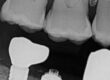
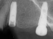
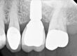
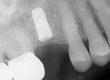
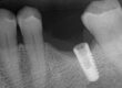
The 02.24.24 cropped pan image (far left) shows the screw fragment fracture residing just above the first implant thread, a Type I or II case. The middle PA image was taken on 03.0.24. Note the position of the fragment top, now at or below the first implant thread. The right preop image, a 25x microscope Helicon focus stacked image, shows the eccentric drilling effort, directed toward 11 o’clock, with the semi-lunar retained screw fragment toward 4 o’clock.
As the screw fragment was non-mobile, it required mobilization with a concentric technique to avoid further implant thread damage. This was accomplished by establishing a concentric spot using a surgical length ¼ round bur in a high speed handpiece, under microscope guidance. Normally, this procedure would be accomplished with a spot drill in a very precision custom drill guide, but the side wall created by the first eccentric recovery attempt would literally push the spot drill off axis and the created dimple, though more concentric, would still be off axis. Once the starting “dimple” was satisfactorily established concentrically on the screw fragment, a custom .8mm left hand drill, utilizing a precision custom drill guide, was used to center drill the fragment. The plan was to completely drill the fragment to the end, so a screw extractor could be adequately engaged to transfer enough torque to overcome potential thread distortions. Fortunately, in the process of drilling the .8mm bore, the fragment was recovered on the drill. As there was documented prior thread damage, a M1.6 x .35 plug tap followed by the same size bottoming tap were passed through the threads to confirm there were no residual metal burs to complicate the future restorative effort. To assess the thread damage, a polyvinyl impression was made and photographed every 90 degrees. The following photographs clearly delineate the damage. While not ideal, I believe this implant is still functional, as the implant has an intact conical interface, as visualized with 25x magnification, and has enough screw threads for the new abutment screw to obtain preload on the abutment screw. Time will tell whether the screw is protected well enough by the implant interface stability to prevent loss of preload and another loose or fractured abutment screw, as it is subjected to future cyclic loading.
")
")
")
")
")
The initial recovery effort had progressed completely eccentric into the implant, and the recovery tool kit was not available at the time of the appointment to evaluate stability and accuracy provided. I was able to contact the Salvin area representative and he brought one to the office for review. While this did not allow me to evaluate it in depth, it was certainly an interesting experience. The goal of this evaluation effort was to see how this kit could drill off axis to the extent it did.
First, for background information, there are several reasons why a drilled bore may not be concentric, even with guidance. So these are the parameters that come to mind, which may help evaluate tooling in the future:
- The guide was not made concentric, so the guiding bores do not aline with the interface.
- The tolerance fit of the drills to the guide is not adaquate, which allows for the drill to wander and drill eccentrically.
- The tolerance fit of the guide to the implant interface is not adequate, again allowing eccentric drilling.
- The handle system, while designed to hold the guide stable, often does just the opposite, if the tolerance fit of the guide to the implant is not secure or stable. Many implant interfaces do not offer enough stability to resist the torsional leverage a handle system can exert.
- There was no confirmed, concentric starting point with a spotting drill, without which the drill is allowed to wander while starting the bore.
- As these drills are small and flexible, the drills can flex, especially when starting the bore. This is a big reason for fractured drills, as this eccentric drilling side loads the drill. As the bore is deepened, the loading increases, fracturing the drill and if not, the eccentric error increases.
When reviewing the recovery kit, the first aspect was to understand how the guide fit the Astra Tx Aqua interface. None of the guide sleeves fit. The Salvin rep then phoned the company that manufactors the kit and the developer confirmed there was no guide sleeve, as of yet, that interfaces with this implant. This is consistant with point 3 above and this alone could have created this problem, but there’s more. When the drill was inserted into the guide, the amount of “play” between the drill and the guide was significant. While I couldn’t measure it in order to quantify the amount, I did place a TSV guide onto a corresponding sized, open TSV analog. Due to the loose tolerance fit of the twist drill to the guide, the drill could be manipulated back and forth into the implant threads. This was covered as point 2 above. The last point I will make is covered in point 4 above. I abandoned the use of the classic handle system many years ago for the reasons listed above. I had used Triad resin gel for years to make custom indexed guides, until Dentsply discontinued the product. I have now found a clear orthodontic resin (Orthocryl LC) which works very well. These custom guides can be made very quickly, are indexed to adjacent teeth, and are removable to clean debris from drilling and to evaluate progress with the microscope.
When the above information is understood, as it applies to this case, it is clearly understandable why implant damage was done. Overall, I would say a kit with a limited number of guides and loose tolerances between the guide and the guided rotary instruments, are most likely to produce this type of failed attempt. If used, extreme caution should be exercised and microscopically checked often when using any rotary instrument. If available, a guide system that satisfies all six of the above requirements should be utilized. This includes using a spotting drill with the resulting spot verified microscopically before proceeding to actual drilling. The operator should know the diameter of the screw before starting the recovery so the initial drill size diameter can be appropriately sized to keep enough side wall in the fragment for stability, which prevents expansion of the fragment when engaging a screw extractor. Remember, the dimensions are small and tolerances are tight and there is very little room for eccentric error. However, I can say with total confidence and a lot of experience, with the correct visualization, precision tools, and proper training to understand the process, recovering these fractured abutment screws is nearly totally predictable, especially if there have not been previous attempts.
For additional information regarding these procedures, there are additional case studies posted on our website.
Charlie Mastrovich, DDS